- 您现在的位置:买卖IC网 > Sheet目录3832 > AT87C52X2-3CSUM (Atmel)IC 8051 MCU 8K OTP 40MHZ 40DIP
36
TS8xCx2X2
4184I–8051–02/08
Electrical
Characteristics
Absolute Maximum
Ratings(1)
Power Consumption
Measurement
Since the introduction of the first C51 devices, every manufacturer made operating Icc
measurements under reset, which made sense for the designs were the CPU was run-
ning under reset. In Atmel new devices, the CPU is no more active during reset, so the
power consumption is very low but is not really representative of what will happen in the
customer system. That’s why, while keeping measurements under Reset, Atmel pre-
sents a new way to measure the operating Icc:
Using an internal test ROM, the following code is executed:
Label:
SJMP Label (80 FE)
Ports 1, 2, 3 are disconnected, Port 0 is tied to FFh, EA = Vcc, RST = Vss, XTAL2 is not
connected and XTAL1 is driven by the clock.
This is much more representative of the real operating Icc.
DC Parameters for
Standard Voltage
TA = 0°C to +70°C; VSS = 0 V; VCC = 5V ± 10%; F = 0 to 40 MHz.
TA = -40°C to +85°C; VSS = 0 V; VCC = 5V ± 10%; F = 0 to 40 MHz.
Ambiant Temperature Under Bias:
C = commercial......................................................0°C to 70°C
I = industrial ........................................................-40°C to 85°C
Storage Temperature .................................... -65°C to + 150°C
Voltage on VCC to VSS .........................................-0.5V to + 7 V
Voltage on VPP to VSS .......................................-0.5V to + 13 V
Voltage on Any Pin to VSS..........................-0.5V to VCC + 0.5V
Power Dissipation ........................................................... 1 W(2)
Notes: 1.
Stresses at or above those listed under “ Absolute
Maximum Ratings” may cause permanent dam-
age to the device. This is a stress rating only and
functional operation of the device at these or any
other conditions above those indicated in the
operational sections of this specification is not
implied. Exposure to absolute maximum rating
conditions may affect device reliability.
2. This value is based on the maximum allowable die
temperature and the thermal resistance of the
package.
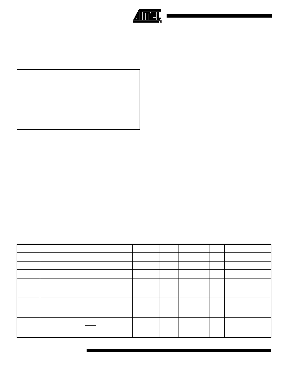
Table 22. DC Parameters in Standard Voltage
Symbol
Parameter
Min
Typ
Max
Unit
Test Conditions
VIL
Input Low Voltage
-0.5
0.2 VCC - 0.1
V
VIH
Input High Voltage except XTAL1, RST
0.2 VCC + 0.9
VCC + 0.5
V
VIH1
Input High Voltage, XTAL1, RST
0.7 VCC
VCC + 0.5
V
VOL
Output Low Voltage, ports 1, 2, 3 (6)
0.3
0.45
1.0
V
IOL = 100 A(4)
IOL = 1.6 mA(4)
IOL = 3.5 mA(4)
VOL1
Output Low Voltage, port 0 (6)
0.3
0.45
1.0
V
IOL = 200 A(4)
IOL = 3.2 mA(4)
IOL = 7.0 mA(4)
VOL2
Output Low Voltage, ALE, PSEN
0.3
0.45
1.0
V
IOL = 100 A(4)
IOL = 1.6 mA(4)
IOL = 3.5 mA(4)
发布紧急采购,3分钟左右您将得到回复。
相关PDF资料
PIC16C924-04/L
IC MCU OTP 4KX14 LCD DVR 68PLCC
PIC16F767-I/SO
IC PIC MCU FLASH 8KX14 28SOIC
PIC24FJ64GA310-I/PF
MCU 16BIT 64KB FLASH 100TQFP
DSPIC33FJ64GP202-E/MM
IC DSPIC MCU/DSP 64K 28-QFN
PIC16F876A-I/ML
IC MCU FLASH 8KX14 A/D 28QFN
PIC16F876A-I/SO
IC MCU FLASH 8KX14 EE 28SOIC
PIC16F876A-I/SP
IC MCU FLASH 8KX14 EE 28DIP
AT87C51RD2-3CSUM
IC 8051 MCU 64K OTP 40MHZ 40DIP
相关代理商/技术参数
AT87C52X2-3CSUV
功能描述:8位微控制器 -MCU Microcontroller
RoHS:否 制造商:Silicon Labs 核心:8051 处理器系列:C8051F39x 数据总线宽度:8 bit 最大时钟频率:50 MHz 程序存储器大小:16 KB 数据 RAM 大小:1 KB 片上 ADC:Yes 工作电源电压:1.8 V to 3.6 V 工作温度范围:- 40 C to + 105 C 封装 / 箱体:QFN-20 安装风格:SMD/SMT
AT87C52X2-RLRUM
功能描述:8位微控制器 -MCU 0.5um RoHS:否 制造商:Silicon Labs 核心:8051 处理器系列:C8051F39x 数据总线宽度:8 bit 最大时钟频率:50 MHz 程序存储器大小:16 KB 数据 RAM 大小:1 KB 片上 ADC:Yes 工作电源电压:1.8 V to 3.6 V 工作温度范围:- 40 C to + 105 C 封装 / 箱体:QFN-20 安装风格:SMD/SMT
AT87C52X2-RLTUL
功能描述:8位微控制器 -MCU C72X2C52 0.5m OTP RoHS:否 制造商:Silicon Labs 核心:8051 处理器系列:C8051F39x 数据总线宽度:8 bit 最大时钟频率:50 MHz 程序存储器大小:16 KB 数据 RAM 大小:1 KB 片上 ADC:Yes 工作电源电压:1.8 V to 3.6 V 工作温度范围:- 40 C to + 105 C 封装 / 箱体:QFN-20 安装风格:SMD/SMT
AT87C52X2-RLTUM
功能描述:8位微控制器 -MCU C72X2 C52 0.5 m X 2 OTP 0.5 NV RoHS:否 制造商:Silicon Labs 核心:8051 处理器系列:C8051F39x 数据总线宽度:8 bit 最大时钟频率:50 MHz 程序存储器大小:16 KB 数据 RAM 大小:1 KB 片上 ADC:Yes 工作电源电压:1.8 V to 3.6 V 工作温度范围:- 40 C to + 105 C 封装 / 箱体:QFN-20 安装风格:SMD/SMT
AT87C52X2-RLTUV
制造商:ATMEL 制造商全称:ATMEL Corporation 功能描述:8-bit Microcontroller 8 Kbytes ROM/OTP, ROMless
AT87C52X2-SLRUL
功能描述:8位微控制器 -MCU Microcontroller RoHS:否 制造商:Silicon Labs 核心:8051 处理器系列:C8051F39x 数据总线宽度:8 bit 最大时钟频率:50 MHz 程序存储器大小:16 KB 数据 RAM 大小:1 KB 片上 ADC:Yes 工作电源电压:1.8 V to 3.6 V 工作温度范围:- 40 C to + 105 C 封装 / 箱体:QFN-20 安装风格:SMD/SMT
AT87C52X2-SLRUM
功能描述:8位微控制器 -MCU Microcontroller RoHS:否 制造商:Silicon Labs 核心:8051 处理器系列:C8051F39x 数据总线宽度:8 bit 最大时钟频率:50 MHz 程序存储器大小:16 KB 数据 RAM 大小:1 KB 片上 ADC:Yes 工作电源电压:1.8 V to 3.6 V 工作温度范围:- 40 C to + 105 C 封装 / 箱体:QFN-20 安装风格:SMD/SMT
AT87C52X2-SLSUL
功能描述:8位微控制器 -MCU OTP C52/8K 40MHZ 3V COM RoHS:否 制造商:Silicon Labs 核心:8051 处理器系列:C8051F39x 数据总线宽度:8 bit 最大时钟频率:50 MHz 程序存储器大小:16 KB 数据 RAM 大小:1 KB 片上 ADC:Yes 工作电源电压:1.8 V to 3.6 V 工作温度范围:- 40 C to + 105 C 封装 / 箱体:QFN-20 安装风格:SMD/SMT